Project Overview
This project investigated the aerodynamic performance of four parametrically generated airfoil geometries through computational fluid dynamics (CFD). The primary objective was to evaluate how variations in airfoil geometry influence aerodynamic loading, pressure distribution, airflow velocity, and overall aerodynamic efficiency.
Working within a team of five, I took responsibility for the computational aerodynamic investigation, using airfoil parameters generated by my teammates through Latin Hypercube Sampling (LHS).
I independently developed two-dimensional computational models using Autodesk Fusion 360 and ANSYS CFX, conducted a mesh independence investigation, assessed residual convergence, and evaluated aerodynamic performance across varying angles of attack.
Following the simulations, I compiled and communicated my findings to the remaining team members, providing the foundation for the aerodynamic analysis incorporated into the final group report.
Engineering Problem
Airfoil geometry significantly influences aerodynamic performance through its effect on pressure distribution, airflow acceleration, and the generation of lift and drag.
The engineering challenge was to determine how variations in maximum thickness, maximum camber, and maximum camber position influence the aerodynamic characteristics of four candidate airfoils.
A secondary challenge was ensuring that the computational simulations produced sufficiently accurate and converged results to support meaningful comparisons between different geometries.
The project therefore aimed to investigate the relationship between airfoil shape and aerodynamic performance while establishing a reliable computational methodology for evaluating candidate designs.
Computational Methodology
Parametric Airfoil Modelling
The investigation began with four airfoil configurations defined using Latin Hypercube Sampling, a Design of Experiments methodology employed by other members of the project team.
The three principal design variables were maximum thickness, maximum camber, and maximum camber position.
Using these parameters, I developed the computational geometries required for the two-dimensional aerodynamic investigation in Autodesk Fusion 360.
The geometries were subsequently prepared for analysis within ANSYS CFX, allowing the airflow surrounding each airfoil to be simulated.
CFD Model Development
The computational investigation was conducted using ANSYS CFX.
Each airfoil was positioned within a computational fluid domain representing the surrounding airflow.
Inlet, outlet, and wall boundary conditions were applied to simulate the aerodynamic environment under controlled conditions.
The simulations were used to investigate aerodynamic forces, pressure distributions, velocity fields, and streamline behaviour around the four candidate geometries.
Mesh Independence Investigation
An independent mesh refinement investigation was conducted to assess the sensitivity of the numerical results to computational mesh resolution.
Multiple mesh configurations were generated and compared using their predicted lift and drag forces.
The objective was to identify a mesh resolution at which further refinement produced relatively small changes in the aerodynamic predictions.
This investigation was essential for balancing numerical accuracy against computational cost and establishing a consistent mesh for subsequent airfoil comparisons.
Residual Convergence Analysis
Throughout the CFD simulations, I monitored the residual convergence histories to assess the numerical stability and convergence of the solutions.
Residuals were examined across successive solver iterations to determine whether the governing flow equations were approaching a sufficiently converged solution.
This process helped identify simulations requiring additional iterations or adjustments to the numerical setup.
Residual convergence was considered alongside mesh independence when assessing the reliability of the CFD results.
Aerodynamic Performance Analysis
Following mesh refinement and convergence assessment, simulations were conducted for the four candidate airfoil geometries.
The resulting lift and drag forces were compared to evaluate their relative aerodynamic performance.
Additional simulations at varying angles of attack were used to investigate how changes in flow incidence influenced aerodynamic loading and flow behaviour.
Pressure contours and velocity streamlines were examined to interpret how differences in airfoil geometry affected local pressure gradients, airflow acceleration, and flow direction.
The resulting data was compiled and communicated to the other members of the group for inclusion in the final technical report.
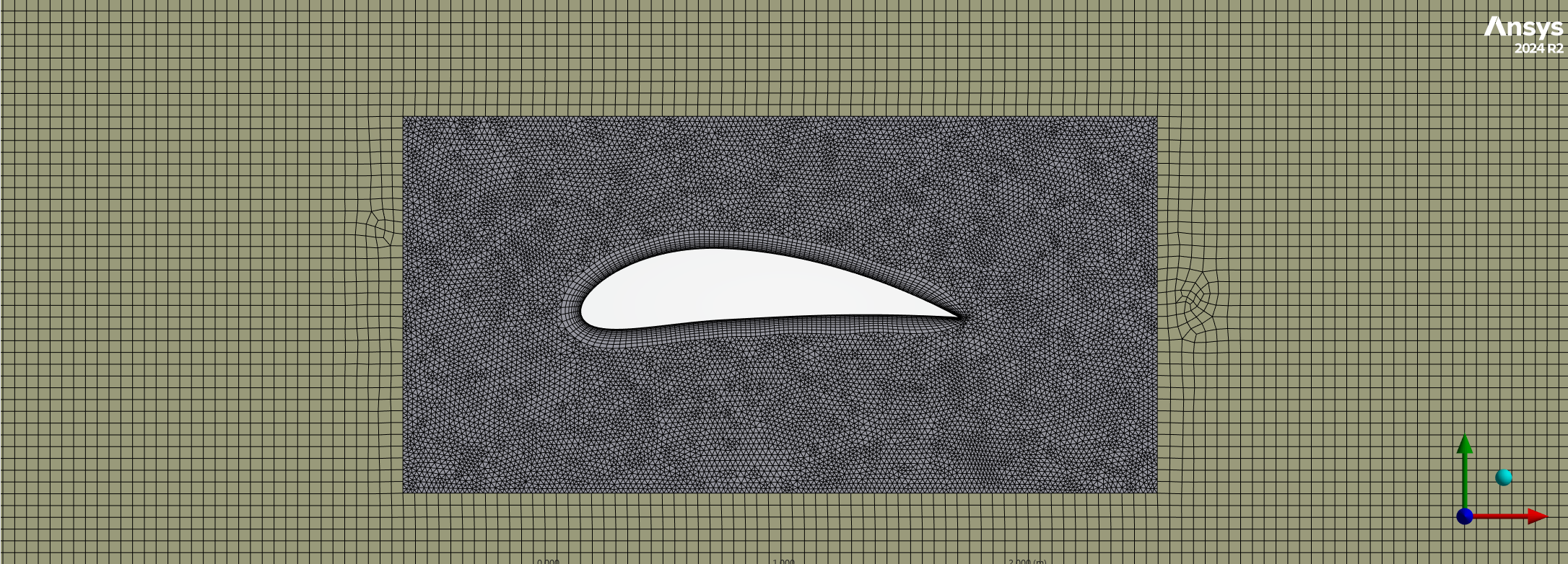
Mesh Independence Investigation (Optimal Mesh 0.02 inner 0.05 outer)
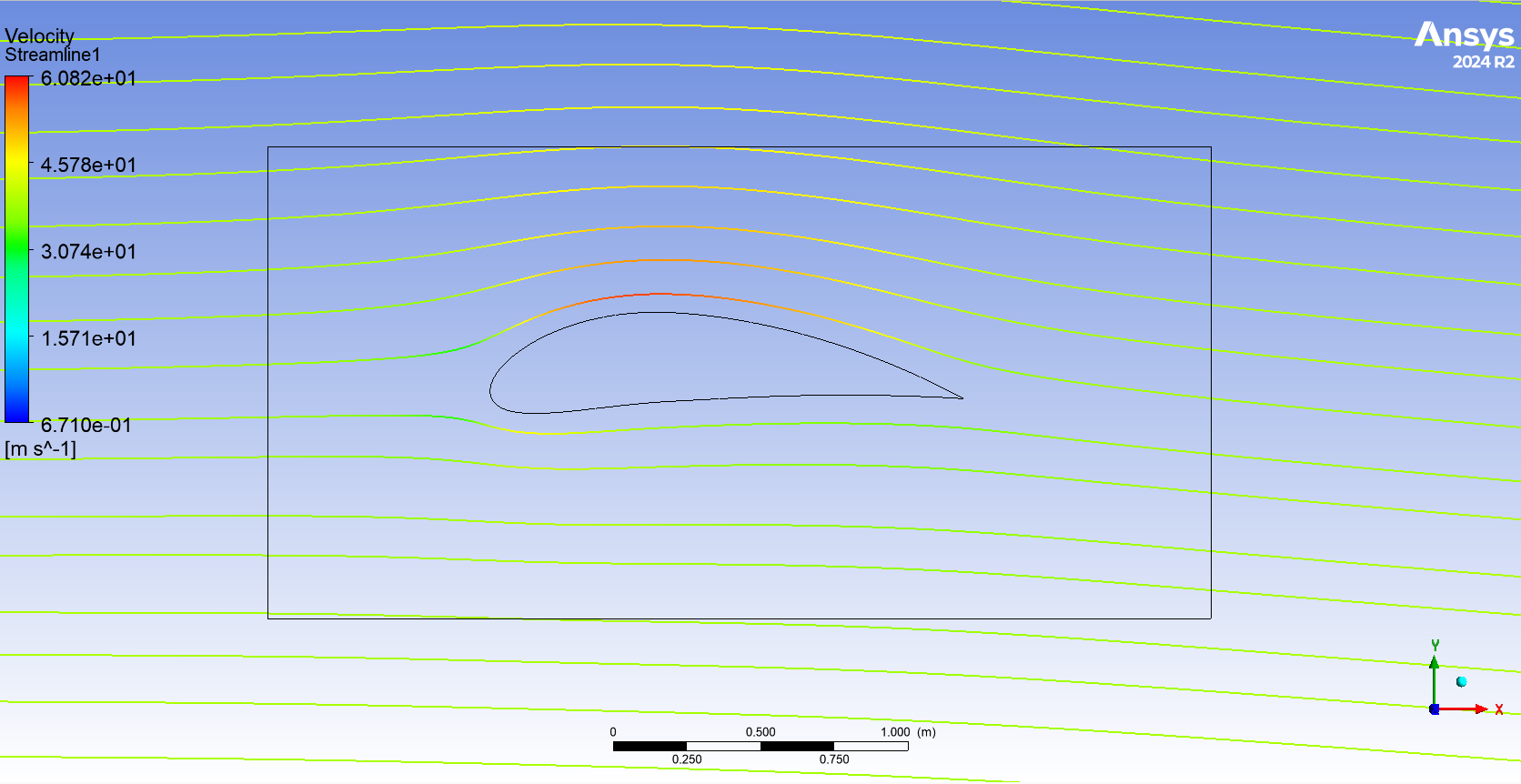
Streamline Contour (Optimal Mesh)
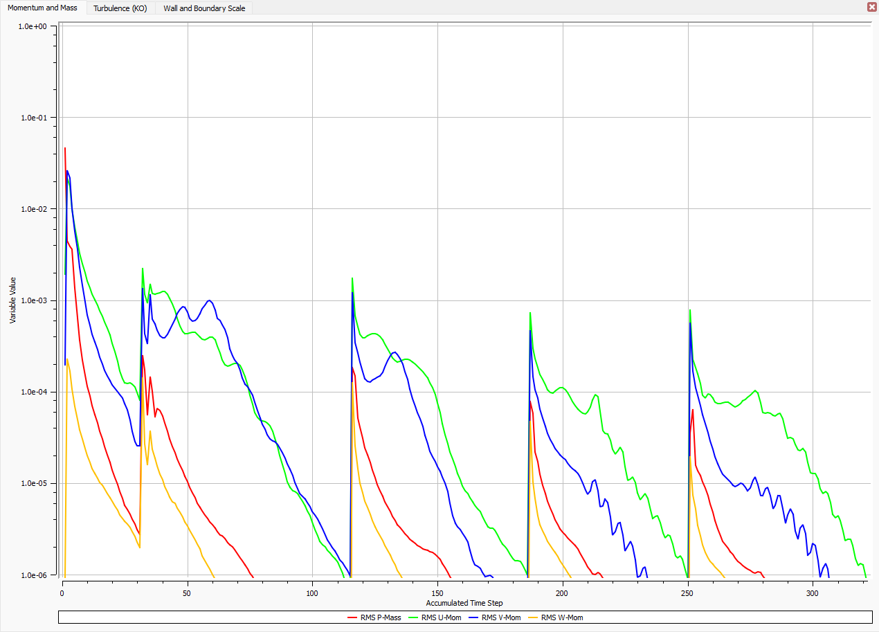
Convergence Criteria (Optimal Mesh)
Engineering Constraints and Challenges
Computational Mesh Resolution
The accuracy of CFD predictions is influenced by computational mesh resolution, particularly near the airfoil surface where velocity gradients can be significant. Increasing mesh density improves spatial resolution but also increases computational requirements.
Numerical Convergence
CFD simulations rely on iterative numerical methods to solve the governing flow equations. Insufficient convergence can produce unreliable aerodynamic predictions, requiring careful assessment of residual histories before interpreting results.
Computational Domain and Boundary Conditions
The dimensions of the computational domain and the selection of boundary conditions can influence the predicted airflow around an airfoil. Maintaining consistent domain and boundary conditions was important when comparing the four geometries.
Parametric Geometry Variation
Each candidate airfoil contained different combinations of maximum thickness, camber, and camber position. Consistent simulation conditions were required to ensure that differences in aerodynamic performance could be attributed primarily to changes in geometry.
Two-Dimensional Modelling
The investigation was restricted to two-dimensional simulations, meaning three-dimensional aerodynamic effects such as wingtip vortices, spanwise flow, and finite-wing induced drag were not represented.
Results and Aerodynamic Analysis
The computational investigation enabled comparison of the aerodynamic performance of four parametrically generated airfoil configurations.
Pressure Distribution
Pressure contour plots were used to investigate the influence of airfoil geometry on pressure variation around the upper and lower surfaces.
Differences in camber and thickness influenced the simulated flow field, providing insight into the relationship between airfoil shape and aerodynamic loading.
Velocity and Streamline Behaviour
Velocity streamlines were examined to investigate airflow acceleration and changes in flow direction around each airfoil.
These visualisations supported interpretation of how airfoil geometry influenced the surrounding flow field and contributed to the observed aerodynamic forces.
Lift and Drag Characteristics
The predicted lift and drag forces were compared across the four candidate designs to evaluate their relative aerodynamic performance.
The investigation also considered the effects of varying angle of attack on aerodynamic loading, providing a basis for understanding how each geometry responded to changing flow incidence.
Mesh Independence and Numerical Convergence
The mesh independence investigation assessed the sensitivity of predicted aerodynamic forces to mesh refinement.
Residual convergence analysis was used to evaluate the iterative behaviour of the CFD solutions and support the assessment of numerical reliability.
Together, these investigations provided a technical basis for interpreting the aerodynamic results and comparing the candidate airfoil designs.
Engineering Conclusions and Recommendations
This project developed my understanding of how airfoil geometry influences aerodynamic performance and highlighted the importance of numerical verification in computational fluid dynamics.
The investigation provided practical experience in preparing computational geometries, conducting CFD simulations, evaluating mesh sensitivity, and interpreting numerical convergence.
It also demonstrated how pressure contours, velocity streamlines, and aerodynamic force predictions can be used collectively to assess the performance of different airfoil configurations.
Further investigations could include:
Additional mesh refinement to increase confidence in the numerical predictions.
Experimental validation of CFD results using wind tunnel measurements or published aerodynamic data.
Investigation of a wider range of angles of attack, particularly near stall.
Three-dimensional aerodynamic modelling to account for finite-wing effects.
Expansion of the parametric study to investigate additional airfoil geometries and operating conditions.
Skills and Technical Experience
Computational Fluid Dynamics: ANSYS CFX, numerical simulation setup, aerodynamic force prediction, pressure contour interpretation, and velocity streamline analysis.
CAD and Parametric Modelling: Autodesk Fusion 360, airfoil geometry development, and computational domain preparation.
Numerical Verification: Mesh independence investigations, residual convergence monitoring, and assessment of numerical solution reliability.
Aerodynamic Analysis: Airfoil geometry, lift and drag characteristics, pressure gradients, flow acceleration, and angle-of-attack effects.
Technical Communication: Compilation and presentation of computational results for incorporation into a collaborative engineering report.
Team Collaboration: Independent responsibility for the CFD investigation within a five-person engineering team, including coordination with teammates responsible for parametric design and report preparation.